This layout results in a “wasted spark” operation of the ignition system. This system not only produces a spark in the cylinder on its compression stroke, but also on the companion cylinder which will be on its exhaust stroke, hence the term 'wasted spark'. The cylinder on compression will have a higher pressure present when compared to a cylinder on the exhaust stroke. This results in a larger firing voltage being evident on the cylinder completing its compression stroke.
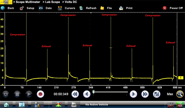
N.B: It must be noted that the polarity of the spark voltage does not change regardless of the operating cycle/stroke of the engine.
Several factors and physical laws must be considered when attempting to gain a full understanding of the ignition system on an internal combustion engine. The following section will outline these in greater detail.
For optimum combustion to take place the timing and the intensity of the secondary circuit spark must be precisely controlled.
Requirements
There are three fundamental requirements for a high-intensity spark to take place:
-
The amount of current flowing in the primary circuit.
-
The turns ratio between the primary winding and secondary winding.
-
The rate of change of magnetic flux density.
A large current flow through the primary winding is required to ensure the winding reaches (or is close to) magnetic saturation.
-
When the ignition coil driver grounds the ignition coil primary winding a current begins to flow through the winding. The current flow “ramps up” due to the inductance of the winding, this is due to the creation of magnetic fields which oppose the current flow.
-
The engine control module "breaks" the circuit and current flow ceases. This results in a voltage becoming induced into the secondary winding due to mutual inductance and into the primary winding due to self-inductance. This system uses “ramp and fire”, this is where the primary ground circuit is open just before the primary winding reaches magnetic saturation. This reduces thermal stress on the coil.
-
The secondary circuit activity is mirrored by the primary circuit. The spark duration and oscillations in the secondary circuit can be observed at this point.
A vehicle that has an anomaly in any of these key areas will have an ignition system fault present.
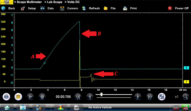
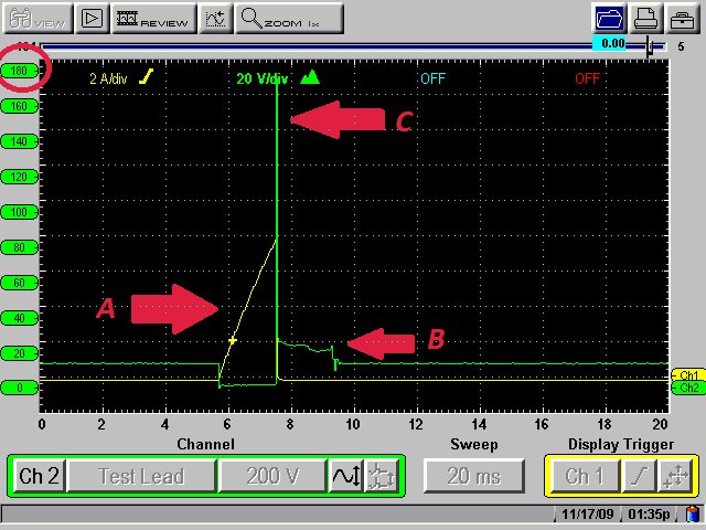
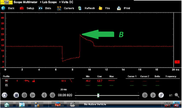
The image below was taken from a vehicle that had a shorted winding. It can be seen from point (A) that the characteristic ramp-up of current flow is missing and the current increases sharply. This short circuit has the effect of altering the turns ratio between the primary winding and the secondary winding. As can be observed from point (B) an ignition misfire is present in the secondary circuit. Another point to note is point (C), a reduction in the induced back EMF in the primary winding.
N.B. the primary circuit voltage waveform mirrors the ignition events in the secondary circuit due to induction.
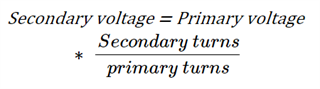
A turns ratio of 100:1 is normal, where the primary winding has 200 turns and the secondary winding has 20,000 turns. If this ratio is altered then the voltage available in the secondary winding will be adversely affected.
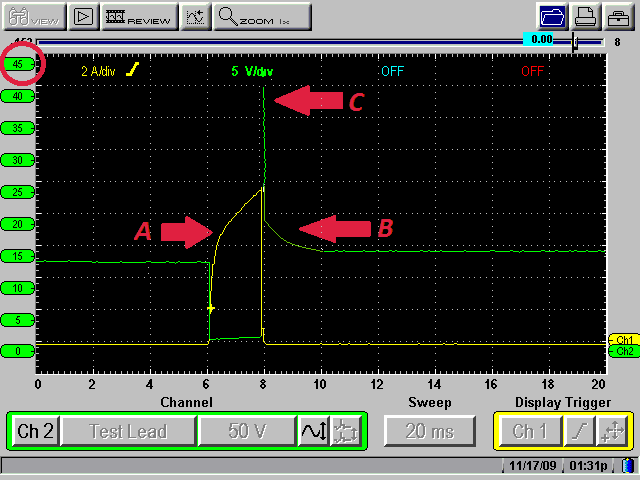
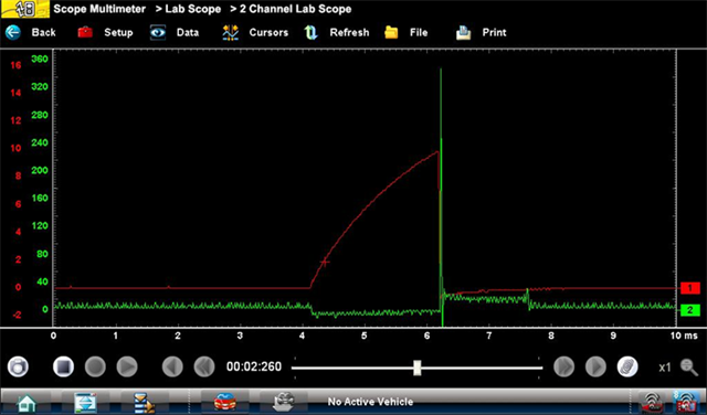
The image below shows the same vehicle after the faulty ignition coil was replaced. Point (A) shows the correct current ramp-up trace for a functioning primary winding. At point (B) it can be clearly observed that correct secondary circuit operation is evident and at point (C) a larger induced voltage is displayed.*
*Normally an induced voltage of 300-400 volts will be observed on the primary waveform, however, see the synopsis at the end for more detail.
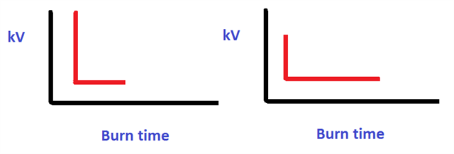
Firing voltage Vs Burn Time
-
When a large firing voltage is required there is less available energy to have a large spark duration. This limits the available energy to maintain the spark (Burntime)
-
When a small firing voltage is required there is more available energy to have a large spark duration.
Faraday’s Law
Another fundamental principle of the ignition system which was previously mentioned is the rate of change of magnetic flux. This phenomenon is called Faraday’s law and is as follows:
The magnitude of the induced EMF is proportional to the rate of change in flux.
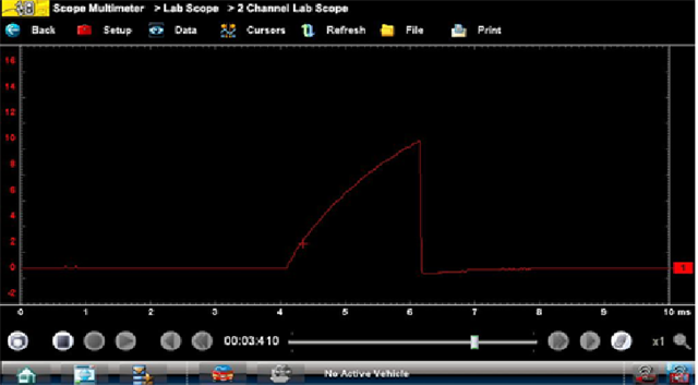
The rate of change of magnetic flux can be reduced due to a faulty ignition coil driver or a high resistance in the control circuit. The image below shows a current ramp from a vehicle with such a fault. The ignition coil drivers for this vehicle are located in the engine control module. Point (A) shows how the primary winding was delayed in having the current flow switched off. And the current was allowed to dissipate away rather than being switched off quickly.
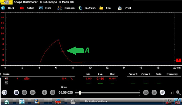
The next image shows the primary circuit voltage, there is a complete absence of self-induction (back EMF) and there is no activity taking place in the secondary circuit.
Once the engine control module was repaired the ignition coil performed correctly, an ignition coil driver was replaced. See the post repair image below:
The current ramp also shows clean and fast switching of the primary circuit:
Renault System Layout
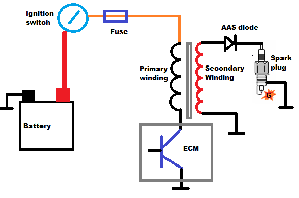
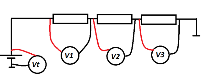
Now with a reasonable understanding of the fundamental principles of ignition systems, we can consider the Renault system which must abide by the same rules to create a satisfactory spark but is controlled slightly differently. As previously stated the system operates on the “wasted spark” principle. This is not unusual, however, normally the companion cylinders share the same secondary winding. Another way of creating this type of system is by having two primary windings in series and a separate secondary circuit for each spark plug. The other side of the secondary winding is connected to the primary winding. The secondary circuit must be complete to allow the current to flow. Again a number of physical laws can be observed by analysing this circuit.
Lenz’s Law
Lenz’s law states that:
The direction of the induced EMF is always such as to oppose the change producing it
The diagram demonstrates this:
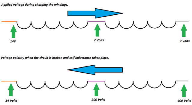
This diagram shows us two key points. Firstly the ignition coil fitted to these vehicles is a 6-volt coil, as both windings have the same resistance and both windings are in series with one another.
Secondly, another law can be proven:
Kirchhoff’s Law
In a DC circuit, the sum of the voltage drops is equal to the applied voltage.
Synopsis:
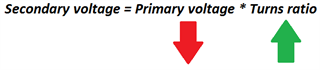
It is evident from this information that there is a lower voltage induced into the primary winding than would normally be observed (200 volts across each winding in this case, normally 350 to 400 volts). However, this has no effect on the firing voltage or spark duration in the secondary. Returning to the law of transformers, if the applied primary voltage is reduced then the turns ratio must increase proportionally to allow for an increased secondary voltage.

The secondary voltage from all four ignition coils is in excess of 40,000 volts and has a spark duration of approximately 1 millisecond when firing on the compression stroke.
Activation Arc Suppression Diode
One final point to note for direct ignition coils, that don’t utilise wasted spark, a diode is required to ensure a spark doesn’t take place at the spark plug when current begins to flow through the primary winding. This is referred to as a switch on spark.
The diode is in series with the secondary winding and the spark plug.