Our next Technical Focus article goes into a fix for a vehicle that had a discharged battery but couldn’t be restarted using normal methods…
By Damien Coleman
A certain amount of caution is necessary when attempting to start vehicles which have a discharged battery. Recently I was asked to investigate a problem with a 2006 Opel Astra that had arisen after the owner had left the car standing idle for a long time.
Over a period of time the battery discharged, so we attempted to start the vehicle by using a set of jump leads (jumper cables) from another car to the Astra. We will never know what happened next other than the Astra was unable to be started. I then tried to find out why this attempt had failed.
I used the Snap-on VERUS PRO tool to diagnose the fault as I find the wireless scanner module (S3) and four-channel oscilloscope ideal for finding difficult problems.
My favourite feature of this tool is how quickly you can switch between viewing parallel data with the oscilloscope module and viewing serial data with the scanner module.
Another aspect of this particular tool that I find beneficial is the ability to connect the oscilloscope module (M4) to the display device (D10) via a USB lead.
This allows the user to position the M4 anywhere on the vehicle and view the data on the display device without compromising the data transfer between the scope module and the display device.
Investigating the system voltage
My preliminary investigations showed that the interior light and central door locking worked correctly when I connected a booster pack to the vehicle’s battery. This was an indication that the system voltage was suitable.
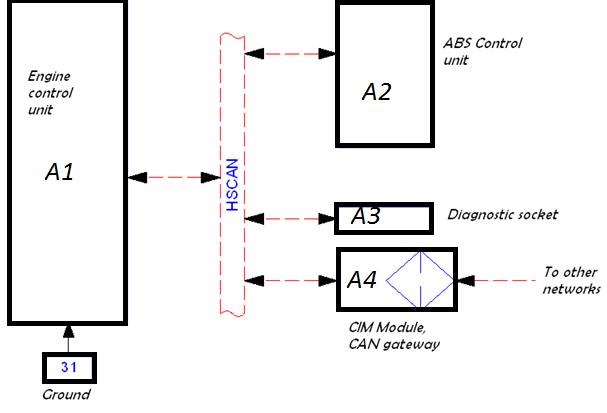
I was able to switch on the ignition but I was unable to communicate with any electronic control module, or ECM, on the high-speed CAN bus network using my scantool – the engine control module, anti-lock brakes (ABS) module and steering column integration (CIM) module.
The CIM acts as the gateway between the high-speed and mid-speed networks. I was able to communicate with several modules on the mid-speed CAN bus network.
These modules were the under-hood electric centre (UEC) and the electric power steering module. The starter motor wouldn’t activate either.
This led the investigation to the high-speed CAN bus network. CAN bus, or controller area network, is a communication protocol used by manufacturers.
This allows fast and accurate communication between modules with strict rules and error detection. The diagram below shows the system layout.
Using some simple circuit tests, involving the oscilloscope and Ohm meter, I was able to identify where the fault was occurring in the circuit.
CAN bus systems use a two-wire network to enhance signal quality and reduce interference.
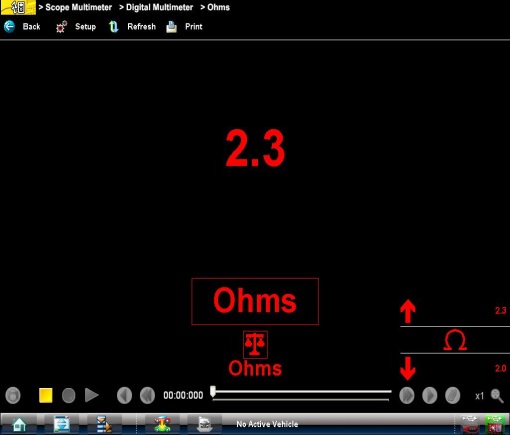
Normally two resistors are built in to the circuit to reduce signal reflection. These are two 120 Ohm resistors wired in parallel to give a total circuit resistance of approximately 60 Ohms.
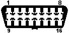
On these vehicles the high-speed CAN bus network can be tested at pin 6 (CAN high) and pin 14 (CAN low) of the 16 pin data link connector. This allows us to test the network very quickly and easily.
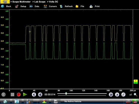
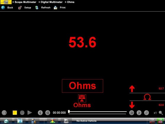
The images below are from a VERUS PRO and show the oscilloscope trace and resistance recorded while the fault was present.
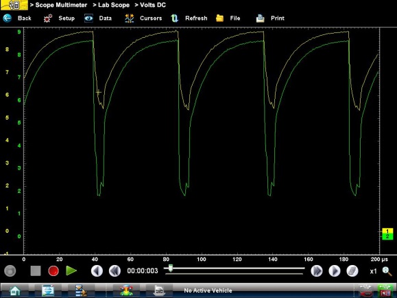
From this data I decided that it was an electronic control module interfering with the CAN network, resulting in a short-circuit within the network.
Note the oscilloscope trace and the lower-than-expected resistance reading. This was disrupting communication between modules. A simple way to find a corrupt ECM is to plug out any module on the affected network while observing the oscilloscope.
Once I plugged out the anti-lock brakes module the network activity returned to normal and the vehicle could be started and driven.
The images below show the same VERUS PRO tests with the ABS module disconnected.
Unfortunately the owner had to have the ABS module replaced in order to return the vehicle to normal operation.
The ideal way to start a vehicle with a discharged battery is to remove the battery from the vehicle and bench charge using a suitable battery charger.
If this isn’t an option, then jump leads should be attached from a running vehicle to the vehicle with the discharged battery.
Always follow the manufacturer instructions outlined in the manual for connecting the jump leads to both vehicles.
Once the jump leads are correctly connected, allow the running vehicle’s engine to idle for approximately five minutes. This allows the second vehicle to charge the flat battery to a state where the voltage difference between both vehicles is reduced.
Problems normally occur when a large potential (voltage) difference exists between both vehicles. Once the vehicle with the flat battery can be started, leave the jump leads on for several minutes afterwards to reduce the possibility of a voltage spike.
Always use good-quality approved jump leads with built-in voltage suppression to minimise the possibility of being left with a large bill to replace an electronic control module.
Date posted: 11 February 2016