A case study using a misfiring Fiat Punto then looks at the technology behind the ignition systems in today’s vehicles...
The vehicle for this scenario is a 2003 Fiat Punto 1.2L petrol with an engine code 188.A4.000. The vehicle had the engine management light illuminated and was misfiring on two cylinders.
A fault code was stored in the engine control module relating to the ignition coil primary control circuit: P0351 - Ignition Coil "A" Primary Control Circuit/Open.
The oscilloscope is an ideal tool for diagnosing this particular fault. Using the scope the technician can validate the circuit by monitoring the control voltage on the ground side of the ignition coil and the current flow through the primary winding.
This vehicle uses a “wasted spark” ignition system. Two separate ignition coils are fitted to the vehicle and each provides a high voltage spark to two cylinders when required.
Once triggered, the spark is present on companion cylinders during the compression and exhaust strokes. The presence of the ignition spark during the exhaust stroke is the reason the system is called “wasted spark”.
In my experience, on these particular vehicles with this particular fault code the diagnosis is normally a fault with the ground circuit within the engine control module.
The same diagnosis is applicable to P0352 - Ignition Coil "B" Primary Control Circuit/Open, which can occasionally be the fault code stored in the ECM as opposed to P0351.
The engine control module was removed from the vehicle and bench tested. The testing was carried out on a rig setup to actuate the ignition coils and an oscilloscope is used to monitor the circuit.
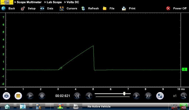
The waveform below shows the ground circuit voltage test:
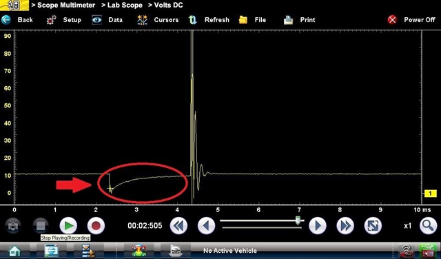
The section of the trace circled should be “pulled” to ground and held at ground potential for the required amount of time the ignition coil should be charged.
This is referred to as the dwell period. A high resistance or poor connection in the ground circuit can limit the amount of current flowing in the primary winding.
The waveform below shows the current draw test:
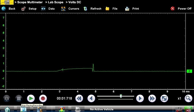
We can see from this trace that the current flow is greatly reduced and the characteristics of the waveform differ from a waveform recorded from a functional vehicle.
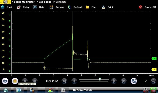
The waveform below shows a two channel test with both ground control voltage and current draw:
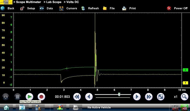
These simple tests confirmed the fault was the ground connection within the engine control module. A new module was fitted to the vehicle based on these test results.
To validate the diagnosis the ignition coil primary control circuit for the second ignition coil was also tested.
The waveform below shows the ground circuit voltage test on the functioning circuit:
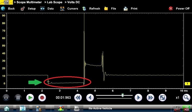
The section of the trace circled shows how the system should function. The ignition coil primary winding is connected to ground for approximately 2 milliseconds.
Although this waveform shows that the connection for this circuit is not perfect either. This could be a sign of a future failure.
The waveform below shows the current draw test on the functioning circuit:
We can see from this trace that the current flow is over four times greater than the circuit with the failure. However the current flow through this circuit is slightly lower than expected but the characteristics of the waveform are correct.
The waveform below shows a two-channel test with both ground control voltage and current draw on the functioning circuit:
Using these simple tests, a fast and accurate diagnosis can easily be made. And most importantly when dealing with expensive components, the technician has the confidence that the part replaced will fix the vehicle and return it to correct operation.
*****
The ignition system for the internal combustion engine has remained fundamentally the same over the last number of decades. The purpose and principle of operation is identical, however the control of the system and malfunction detection has improved in recent years.
The purpose of the ignition system is to deliver a high-voltage spark at the spark plug to ignite the air and fuel mixture.
This spark must have sufficient energy/intensity to create a spark under difficult conditions such as high (compression) pressures within the cylinder, high rates of air turbulence and comparatively lean air and fuel mixtures associated with modern vehicles.
The spark must be of a sufficient duration to support combustion. This results in a stable flame front propagating from the spark plug in a controlled and predicable manner.
The timing of the ignition spark is also critical. Once combustion begins within the cylinder a pressure wave is created.
This pressure acts on the piston, pushing it down the cylinder at a high velocity and thus increasing the rotational force on the engine crankshaft.
Optimum ignition timing is calculated by the engine control module to ensure this pressure increase occurs at the correct time in the cycle.
The ignition coil operates on the principle of mutual induction. The ignition coil consists of two windings, called a primary and secondary winding.
The secondary winding contains many more turns when compared to the primary winding. This allows the coil to operate as a “step-up” device.
The voltage in the primary winding is low voltage (system voltage) and the induced voltage in the secondary winding is high voltage.
The primary winding is supplied with current, and the current flow is controlled by “making and breaking” the ground for the ignition coil. In a simplified form this final stage switching is controlled by an electronic switch called a transistor.
The final stage switching for the primary winding can be integral in the ignition coil assembly or it can be located in the engine control module.
Due to the electrical characteristics of a winding, a strong magnetic field is built up when current is flowing in the circuit.
However, due to the inductance of the winding, the initial build-up of the magnetic field is comparatively slow, thus the high-voltage spark is created when the primary winding ground circuit is disconnected and the winding is initially open circuit.
A sudden change in this magnetic field will cause a voltage to be induced in the secondary winding. The result is a high voltage spark at the spark plug.
From this information we can outline three main criteria for the creation of high voltage in the secondary circuit:
- The amount of current flow in the primary winding (normally 6 to 10 Amps)
- The turns ratio between the primary and secondary winding (normally in the order of 1:50)
- The rate of change of magnetic flux (collapsing of the magnetic field when the ground circuit is initially open circuit)
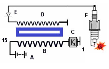
A) Vehicle battery
B) Ignition coil primary winding
C) Engine control module
D) Ignition coil secondary winding
E) Activation arc suppression diode (suppresses unintentional sparks in the secondary)
F) Spark plug
G) High voltage spark
15) Ignition on voltage (terminal assignment)
1) Ignition coil primary circuit control wire (terminal assignment)