In the first of our new series of technical advice articles, Damien Coleman takes a look at some points to note when it comes to Fuel Trim Adaptation...
The fundamental reason for the engine control module to implement fuel trim control is to meet the requirements of the exhaust gas after treatment system, in other words to have the correct conditions for the catalytic converter to work most efficiently.
The cat, often referred to as a three-way catalyst, is designed for two primary purposes: to reduce NOx (oxides of nitrogen) gases, reduce in this case meaning to remove oxygen; and to oxidise CO (carbon monoxide) and HC (hydro-carbons).
NOx gases are created under lean running conditions when in-cylinder combustion temperatures are high.
CO is a by-product of burning a fossil fuel and is an indication of fuel mixture strength. A rich mixture will have a comparatively higher CO exhaust gas content.
HC is unburnt fuel, which can be from incomplete combustion.
So back to fuel trim and the catalytic converter needs the engine to be running at a close to stoichiometric air-to-fuel ratio. This is approximately 14.7 parts of air to 1 part of fuel by mass, i.e. 14.7:1 as a ratio.
However to reduce the NOx gases the system has to operate slightly rich of the stoichiometric ratio to provide CO which creates the following chemical reaction (simplified):
- NOx + CO = N2 (Nitrogen) and CO2 (carbon dioxide)
The system is also required to operate slightly lean of the stoichiometric ratio to provide O2 (oxygen) which creates the following chemical reaction (simplified):
- CO + O2 = CO2
- HC + O2 = CO2 and H2O (water)
So from these examples it is apparent that the fuel system must be capable of “swinging” between rich and lean close to the stoichiometric ratio. This is where the term lambda window comes into play.
The pre-cat (upstream) oxygen sensor provides the feedback information for calculating the amount of fuel required. The control module increases or decreases the injection duration depending on this information. This is referred to as short-term fuel trim (STFT).
The long-term fuel trim (LTFT) is a stored value which accounts for changes in engine condition, wear and tear, etc. The purpose of the LTFT is to get the air/fuel ratio back to stoichiometric (in the event of a fault/normal wear) so the STFT can again cycle between rich and lean operating conditions.
The STFT returns to zero after the engine is switched off. This data is held in the volatile memory of the control module, whereas the LTFT is constantly held in the non-volatile memory.
A final point to note is the both fuel trims are additive, as in:
- STFT + LTFT = total fuel correction
- STFT (+5%) + LTFT (-10%) = total correction of -5%
This means the control module is reducing the fuel injection by 5% from the basic map for that particular operating condition.
So if the basic injection duration map at idle with the engine running at operating temperature is 3 milliseconds then a fuel correction of -5% means the injection duration will now be 2.85 milliseconds. This tells us that the engine is running slightly rich because the instruction is to reduce the fuel injection quantity.
A positive fuel trim value means the system is running lean and fuel needs to be added to the basic map.
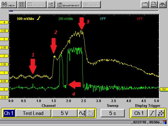
The image above shows a faulty mass airflow meter fitted to a 2004 Opel/Vauxhall Vectra Z16XE. The yellow trace is the mass airflow meter (MAF) signal and the green trace is the pre-catalyst exhaust gas oxygen sensor.
The first concern is the wave type pattern observed from the MAF signal at idle (1). This indicates a potential concern with the MAF sensor. The ideal condition to test a MAF sensor is under wide open throttle conditions, so the throttle is snapped open.
The initial spike in the waveform (2) is referred to as the plenum fill event. The voltage would normally rise to approximately 3 volts, but this particular vehicle only reached 2 volts.
The drop-off in voltage following the plenum fill is normal. This is a void condition, where the air flow is reduced due to pressure equalisation between the inlet manifold and the atmospheric air pressure.
As long as the throttle is held open an increase in airflow velocity results in the airflow again increasing and MAF signal voltage increasing to approximately 4.5 volts (3), again this particular vehicle only reached 3.5 volts.
It should also be noted that the oxygen sensor voltage dropped from approximately 800 millivolts to 100 millivolts during the wide open throttle test.
A high voltage from a narrow band zirconium sensor indicates a rich mixture. A low voltage indicates a lean mixture.
From this data we can see that the vehicle ran lean during full load enrichment. This condition results in power loss.
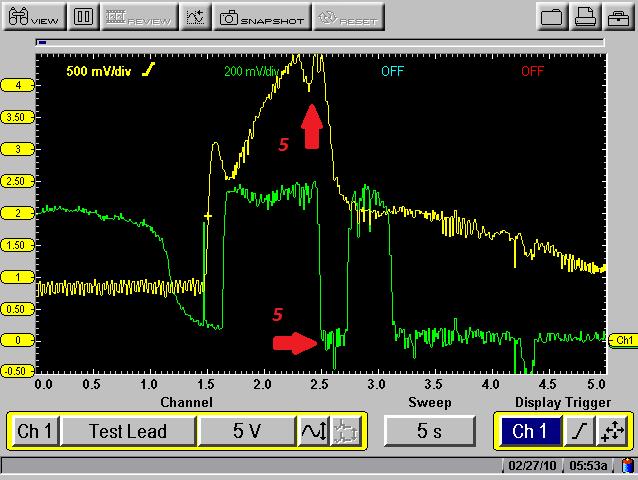
A new mass airflow meter was fitted and the same test was carried out.
The results can be seen below, it must be noted on this waveform that there is a drop off in MAF signal voltage (5) and the oxygen sensor voltage drops to 0 volts (5).
The reason for this is the throttle was held open to the point at which the engine speed limiter was activated.
To limit/reduce engine speed the engine control module shuts off the fuel injectors to cease fuel injection and the throttle valve is closed slightly to reduce airflow.
Date posted: 16 October 2015